Attaching the Wings
[2
hrs]
|
Attaching the Wings |
February 17, 20, 21, 23 & 25 |
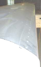 |
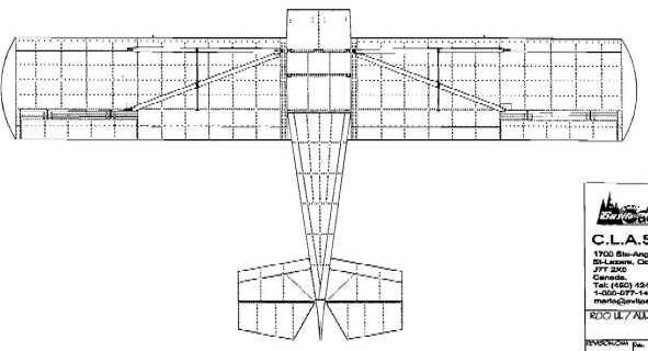
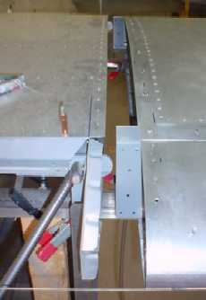
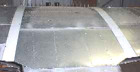
With the wings supported with
temporary brackets, use a sting line along the leading
edges wing-tip to wing-tip to make sure the wings a
perfectly straight (bottom right). You can adjust the
order of the spacers on the wing to get the alignment
correct with the attachment bracket jutting out from the
cabin. Use a spirit level on top of the cabin and wing to
get both surfaces level. TIP: Brace and clamp 1" X 1" angle from one side of the cabin to the other protruding 200mm on either side not only to support the wing, but this will help in aligning the wing top and bottom. At the other end, adjust support brackets to near the correct height with the wing tips raised according to the drawing. |
 |
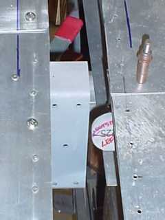 |
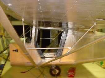
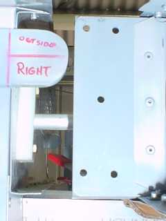
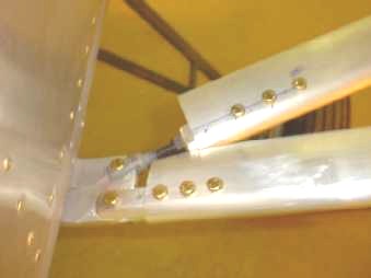
The marker lines of the top of
the wing and the cabin are used to make sure the gap
between the wing and the cabin at the front and the back
are correct. Use clamps to hold the wings in position
before drilling any holes then use a 1/8" drill and
clecos to hold the wings front and back in position
before drilling 5/16" holes for the leading edge and
1/4" for the trailing edge. A metal cover will be
cut and held into position later to cover the gap. TIP: Use cardboard under the wing to protect it's surface from rubbing on the 1" X 1" angle support bracket and slide the aileron control arm through the guide block into the cabin and make sure it slides freely before drilling and bolting the wings to the cabin. |
 |
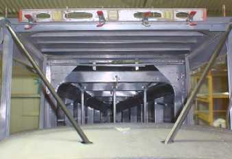 |
TIP: Before cutting the struts and drilling holes, clamp a spirit level on the cabin frame and continually check to see that the aircraft remains level otherwise you could end up with the wings out of alignment and not the required 32mm above the horizontal when the supports at the end of the wing have been removed. It is important to fit the wings to both sides before removing the supports as the aircraft will go out from the horizontal. | |
 |
When fitting the struts to both wings, follow
the instructions in the drawing and make sure they are
raised a further 20mm above the 38mm because when the
supports have been removed after fitting, the weight and
flex in the wings will bring it back to the correct
height above the horizontal. TIP: Dont remove the supports until both wing struts have been fitted and bolted into position |
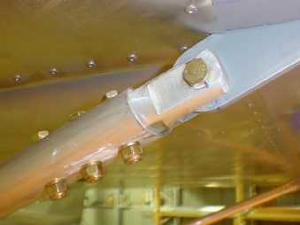 |
The spreaders
have now been constructed and bolted into position
between the struts and the under side of the wing. |
|
March 11 & 18
 |
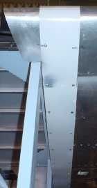
The top fairings
have been cut, drilled and screwed into position with the
trailing edge folded back on itself 20mm so the fairing
on the underside of the wing can be attached. TIP: Make sure the wing is attached in its correct position before marking out and cutting the fairing. Attach the fairing from the trailing edge and work your way back to the leading edge before wrapping under the wing making sure the skin does not buckle or lift to cause a gap. |
|
The next stage
is to cut and fit the fairings for under both wings which
act as the inspection window when working on the fuel
lines, and in particular, the fuel grade plastic tube
used to show the quantity of each fuel in each tank. |
|