Vertical Stabilizer
39 Hours
|
Vertical Stabilizer 39 Hours |
Stabilizer: 29 July, 3 & 5 August
|
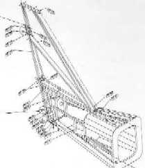
Setting out the
angles for the vertical stabilizer has taken a fair
amount of time to make sure the angle of the vertical
support is correct while remaining vertical to the
workbench and the centre of the fuselage. Before cutting
and drilling and components, take time to set them out
correctly and make sure all pieces are set out in the
order detailed in the plans. |
|
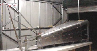
Before riveting or bolting any
of the pieces into its final position, use clecos to hold
each section into place and use a plumb line to make sure
the top centre of the stabilizer is above the centre line
of the table. Even thought the R80 will have a noise wheel, I have installed the fasteners in the tail section to support a tail wheel and spring. |
| As I will be installing a Jabiru 3300 engine
with a clockwise rotation viewed from the pilots seat,
the stabilizer is offset to the left by a line 20mm left
of centre from frame 1. A string line is used from the first frame through to the top of the stabilizer to get the correct angle for the top of the stabilizer. |
 |
|
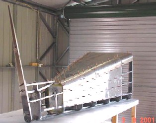
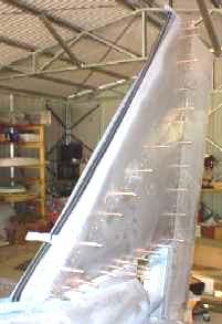
Everything is now
set to dismantle the entire stabilizer in preparation to
debur all the holes, spray paint the metal surfaces that
will come in contact, put it back to gether again
riveting and bolting each section as I go. You maybe able
to see the stringline from frame 1 over the top of the
vertical stabilizer and the plumb bob and square on the
centre line of the workbench. This is make sure that the
stabilizer, while offset to the left, remains vertical
and centre while drilling and attaching the clecos. TIP: Keep the frame fixed to the workbench along the centre line so the tail remains vertical with the frame. |
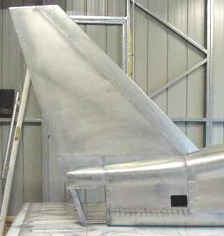
Stabilizer: 10, 17 August
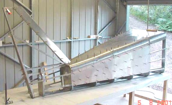
| The skins and leading edge of the stabilizer
have now been completed, however before riveting into
place, the string line and plumb bob are set up again to
make sure that the stabilizer remain vetical with the
workbench. However, don't rivet the U shaped section
under vertical stabilizer to frame 7 at this stage as the
fuselage still needs to be secured to the workbench for
the assembly and fitting of the rubber. When the rudder
is installed, a hole will be cut to allow the rudder
control cable to pass through the skin and connect to the
rudder control arms. TIP: Start riveting from the centre of the skin and work out to the edges in a circle alternating from side-to-side to maintain tension in the skin. The leading edge is the last section to rivet into place. |
 |
December 14
 |
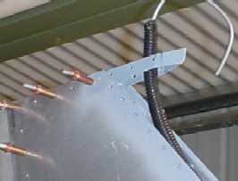
After riveting the vertical stabilizer sometime ago, I decided I would install a tail mounted strobe which fits over the top of the tail section perfectly. The black plastic pipe you can see in the stabilizer is automotive ducting to protect the trobe cable which runs inside the fueslage, up through leading edge of the stabilizer. I removed all the skins as I replaced some of the pop rivets in the tail with solid rivets and replaced the main support 1/8" rivets with 3/16" rivets to give it more support. I know this is not necessary and not included in the plans, however I did it for my own piecec of mind. |
 |
|
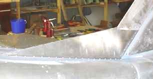
With the skins remover I have also constructed a fin to join the vertical stabilizer to the fuselage. This is not included in the drawings, but when I was visiting Sean and Marlene at the factory in Montreal they were taking about putting a fin on the new four place 164 and have simply used their design. Besides I think it improves the shape but not sure if it will improve the performance. |