Constructing
the Cabin
[190 hrs]
|
[190 hrs] |
Cabin Structure: 23, 28 & 30 September
|
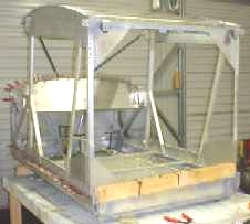
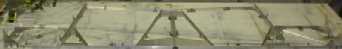
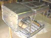
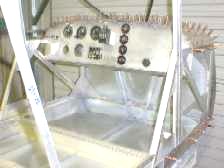
With the bench cleared of the
fuselage, construction has commenced on the cabin with
the assembly of the cabin bottom. Line up all the parts,
secure the frames to the bench using clecos so its
perfectly aligned and flat, the start drilling all the
holes. TIP: Set out one of the spacers for the rivets top and bottom 32mm apart, clamp them together and use it as a template, this way all spacers are the same just in case you mix them up. |
With so many
solid rivets holding each of the three sections together
that makes up the cabin bottom, is it any wonder that the
BushCaddy is one of the most solid kit aircraft available
on the market. |
|
 |
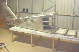
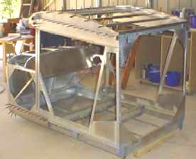
Thought I would lift the fuselage minus the horizontal stabilizers back up onto the workbench and butt it against the cabin bottom just to see what it looks like. Starting to look like an
aircraft. |
 |
 |
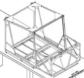
Read all the drawings for the construction of the cabin before strating to cut the individual angel iron length. The drawings show where specific sections need to be adjusted and fitted when in position. Use clecos to hold the sections in place before drilling any holes. | 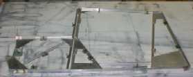 TIP: Mark the pattern on the workbench and individually fit each piece making adjustments as you go. Remember the old saying, mark twice and cut once otherwise you may find yourself wasting material. |
 |
Duplicate the pattern by extending the base line. Clamp the vertical end frames and transfer the measurements so the two frames are identical. |
October: 13, 15, 19, 20, 21, 22, 26, 27, 28 & 29
Now that all
the frames are identical, the templates can be marked and
drilled ready to be riveted to the frame. Each hole in
the frame will need to have a counter sink hole drilled
to take the rivet head. While the spray paint dries, work
on the identical section on the other frame. |
|
|
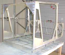
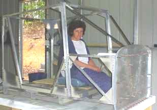
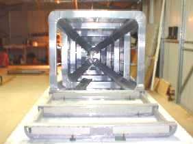
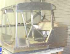
When you place the cabin frames
on the base frame and slide the fuselage back onto the
workbench you start to get a feel for the length of the
aircraft as well as the amount of room there will be
inside the cabin itself. TIP: Use plenty of clamps to hold the cabin frames to the cabin base as well as support angle lengths to keep the correct width of the cabin before cutting, drilling and riveting each of the sections. |
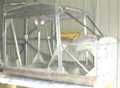
The
construction and solid riveting of the cabin will take a
considerable length of time but don't rush into riveting
without cutting, drilling and fitting all the sections
first and holding them into position with clecos. You
might notice the square on the left side of the cabin,
this is to make sure the frame is square and centre of
the workbench. |
|
|
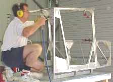
With the cabin frame bolted to
the cabin bottom and the cabin bottom secured to the
workbench so nothing moves, remove the clecos one by one
replacing them with solid rivets as specified in the
drawings. As you rivet the gussets into place you can feel the cabin frame becoming stronger with each rivet. Climbing in an out of the cabin to get the best angle to hold the riveting gun and bucking bar is easy as there is so much room and at this stage all riveting can be performed by one person. |
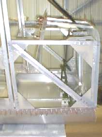
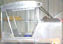
The main
support struts have now been secured to the cabin and the
front frame, also the twin throttle support bracket has
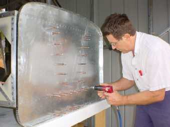
been fitted and secured into position. As I am installing a Jabiru 3300
engine, I kept the cabin
frame clamped to the workbench while holding the firewall
to the structure. This means the bottom surface remained flat to the
workbench. Mark where the angle supports line up against
the rear surface of the firewall. Set out the holes for
the firewall and drill but when it comes time to drill
the holes in the frame, start from the centre and work
outward to the edge so the metal firewall does not buckle. |
|
|
TIP: With the holes drilled in the firewall, start drilling the holes in the cabin frame starting in the centre and working out in a spiral direction inserting clecos at regular intervals. This will ensure the metal firewall pan remains stiff against the frame and doesn't buckle. I have also braced the bottom bracket to the workbench to stop it moving out of place. |
Although Robyn has not been up flying in an ultralight prefering those big birds that have flight attendants serving food and drinks during flight, she was surprised at the size of the cabin and how much leg room there is compared to my last ultralight where your legs were straight out in front. Now all I will have to do is convince her that I sit in the left side as pilot and the passanger sits in the right hand side. Maybe I can talk Robyn Into taking flying lessons ............... |
|
 |
Although the
floor pan is shaped to match the two dimensions it may
not neatly fit where the pan folds from the horizontal to
the vertical. |
 |
|
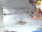
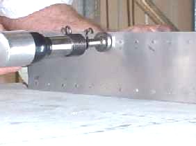
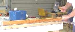
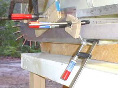
TIP: My
home made dimpling machine, very simple to construct and
easy to operate. All you need is two pieces of wood about
1m long each, a hinge and a dimple set. 1. make a handle for the top piece of timber 2. screw the hinge between the two pieces of timber 3. drill two holes in the timber so the dimple set align 4. use a rubber mallet to stamp the dimple in the aluminium sheet |
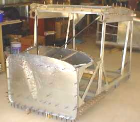 |
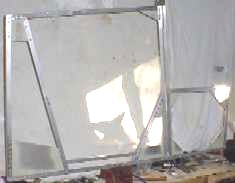
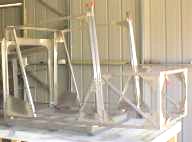
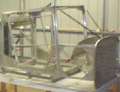
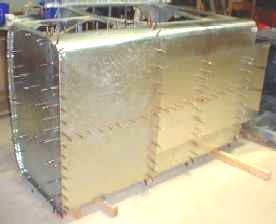
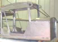
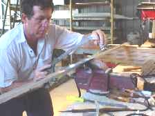
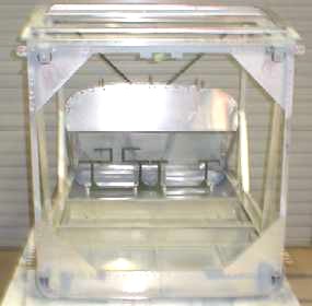
Two views of
the cabin construction while working on the frame on the
floor. At this stage the firewall and the panels that
form the shape for the wings and the top are held into
position with clecos. |
 |
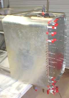
Work has
commenced on fitting the side panels and floor pan to the
cabin frame. Cut and fit the centre panel first drilling
holes along the centre line and fitting the clecos and
working your way up toward the edge. Mark and cut out the
notch for the bracket extending below the cabin and
secure the panels with clecos, this way it will keep the
metal tight against the ribs and the support brackets. |
|
November: 2, 3, 4, 9, 10, 13, 15, 16, 17 & 18
 |
All the riveting of the cabin bottom has now been completed and the brackets holding the under carriage have been drilled and fitted into position before turning the cabin frame back over and putting it back on the workbench so the pedals can be fitted to the floor pan. |
 |
 |
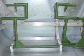
The cabin is
taking shape with the pedals have been bolted to the
floor and the hydraulic break arms slid into position
with a brace onto the angle supporting the firewall. |
 |
The break
pedals move within the nilon blocks that are bolted to
the floor. Adjust the nuts so that they move freely and
that the break pedal that will connect to the hydraulic
cylinder slides all the way into the sleve and moves
freely. |
|
|
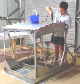
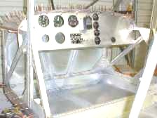
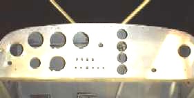
I have
marked out where all the instruments, gauges, control,
switches and fuses etc. are going to be placed on the
dashboard working on the centre line of both pedals and
will drill the holes after all the skins have been cut,
fitted and held with clecos. The length of timber at the
rear of the cabin and the rope is being used to back put
tension on the two springs used to stabilise the pedal
control cables that will be connected once the fuselage
is attached to the cabin. TIP: Don't do any riveting on the dash or any of the skins until all the skins have been cut, fitted and held in position with clecos. |
 |
Attach the
side skins to the cabin frame starting from the top
corner and work toward the front and down toward the
workbench to make sure the skins are kept tight. The
bottom holes will have to be drilled from the inside out
as these have already been drilled to hold the pan into
position. |
 |
With all the
panels removed from the cabin its time to lift the
structure off the workbench and back on to the floor so
the cabin roof can be cut and fitted into position. While
all the panels are removed it is also a good time to blow
all the shavings and bits of aluminum out of the corners
and trapped between the loose skins and the frame. The
structure is so light one person can move it without
difficulty. |
|
 |
Starting to look like an aeroplane with instruments, gauges, switches and fuses being mounted into the dashboard before it is fixed into position, much easire to cut the holes and fit the instruments on the workbend rather than doing it later from inside the cabin. I still have the slip/skid and vertical speed indicator to mount, however the holes are drilled ready for when they arive. |
 |
|
If you
carfully plan the riveting sequence you will be able to
do all but the top row of solid rivets forward of the
dashboard. SEQUENCE: Installation of the pedals and brace to the firewall, tension springs (place a wood block behind the pedals to keep the pedals vertical), hyrdaulic break cylinders and mounting bracket to the floor pan, dual throttle control arm, start riveting the side panels, bolt into position the dashboard, fit the top panel and leave loose while bolting into position the support bars from the firewall frame to the top of the cabin then finally the firewall. Once this is complete, finish riveting. You will only need another person to finish the last of the solid rivets forward to the dashboard. Replace any solid rivets that smile back at you. |
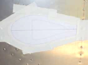 |
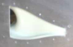
Van Aircraft supply NACA eye-ball valve/director kits for left and right side of the cabin. Use the template to mark the section that is to be cut out of the skin forward of the doors as well as the rivet holes to secure it to the skin. To add strength, cut a template of 0.025" to the same shape as the vent so the rivets secure into metal and not the plastic. |
 |
| TIP: The plans show the dimensions for drilling the holes and mounting the guide blocks for the aileron push rods to enter the cabin. I would recommed that before marking you decide at this point which push rod will go on top of the control arm and which one will go underneath, mark and drill the holes accordingly. This way, minimum pressure will be put on the push rods and the drag will be minimised otherwise you might fine the side-to-side movement of the joy stick a little stiff. |  |
|
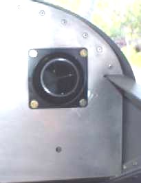 |
With plenty of room on the dashboard to mount the eye-ball valve/director, I have mounted both units in line with the dual throttle control to keep balance with the other instruments and controls and this will ensure they are in easy reach and will direct fresh air onto the face. I could have mounted them under the dash panel but I wanted to keep obstructions away from the legs. |
 |